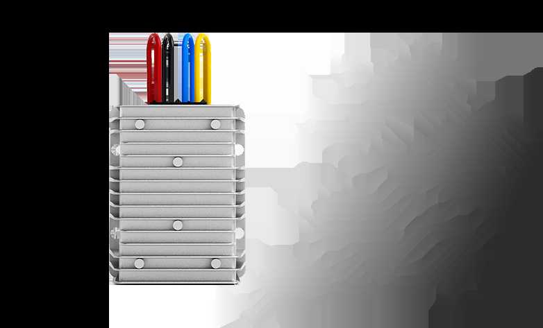

DC-DC Buck converter is an important type of switched mode power supply (SMPS) used to convert the input voltage to a lower stabilized output voltage. In practice, when the load increases, the Buck converter adjusts its operation according to the load demand to ensure the stability of the output voltage. Especially for the DC-DC Buck converter offered by buckboostconverter.com, the core function is to regulate the energy transfer through high-frequency switching elements (e.g., MOSFETs) and store the energy through an inductor to realize the buck conversion. Fine control of this process stabilizes the output voltage under dynamic load conditions.
However, conventional Buck converters may suffer from stability problems when the load changes drastically. In particular, the original Voltage-Second Balance principle may not continue to work effectively during dynamic adjustment. The Voltage-Second Balance principle usually relies on flux changes to keep the output voltage stable, but when the load increases, this principle cannot cope with the rapidly changing current demand, resulting in system instability or output voltage deviation from the expected value. At this point, if the secondary MOSFETs are not turned off in time within the set time, a short-circuit problem may be caused, which can impair the reliability of the system.
In buckboostconverter.com's DC-DC Buck converter designs, special attention is paid to the challenges posed by these dynamic adjustments. To counteract this, buckboostconverter.com utilizes a more refined control strategy. For example, during high-frequency switching, voltage second balancing failures may cause errors to accumulate and affect voltage control accuracy. Therefore, designers need to utilize a more efficient PWM (pulse width modulation) control method combined with a precise feedback control mechanism to correct this instability. By adjusting the switching frequency and duty cycle, buckboostconverter.com's DC-DC Buck converter ensures that the output voltage remains stable despite large load variations.
The DC-DC Buck converter from buckboostconverter.com uses synchronous rectification to improve the conversion efficiency of the system. In synchronous rectification, two MOSFETs are used as replacement elements for a conventional diode, with the aim of reducing the energy loss caused by the forward voltage drop of the diode, thus improving the overall efficiency. The advantage of using synchronous MOSFETs over the conventional diode rectification scheme is that when the MOSFETs are conducting, their voltage drop is low and almost zero, thus reducing the energy loss and improving the efficiency of the system.
In the design of buckboostconverter.com, particular attention is paid to the timing control of synchronous rectification. Specifically, the on and off timing of the switching elements must be precisely synchronized to avoid cross conduction (shoot-through) conditions between MOSFETs. To achieve this, buckboostconverter.com employs a precise PWM control technique, which makes the operating states of the two MOSFETs perfectly synchronized by adjusting the switching timing of the upper MOSFET and the lower MOSFET. Especially at lighter loads, the controller switches off the lower MOSFET, simulating its behavior as a diode, thus improving efficiency.
However, even the synchronous rectification technique faces some challenges. First, the switching delay can vary from MOSFET to MOSFET due to some deviation in the gate charge and threshold voltage of the MOSFET. This delay may lead to inconsistent on-time of the MOSFETs, thus affecting the overall performance of the system. To counteract this problem, buckboostconverter.com's design avoids unwanted cross-conductivity between MOSFETs by delaying the switching timing of the lower MOSFET so that it turns on only when the gate voltage of the upper MOSFET drops below the threshold.
In addition, the effect of the accuracy of the peripheral components on the switching timing has been specifically considered in the design of buckboostconverter.com's DC-DC Buck converter. Due to errors in peripheral resistors and parameters such as parasitic inductance and parasitic capacitance, the gate voltage of the MOSFET may generate pulses which create spurious voltage spikes (VGS') at the gate terminal. If VGS' is less than the MOSFET turn-on threshold voltage (VGS(TH)), the MOSFET will not turn on. Therefore, the goal of the design is not to completely eliminate the effect of VGS', but rather to minimize it by ensuring that VGS' always remains below VGS(TH) under all operating conditions to avoid false turn-on of the MOSFET.
- Details
- 5 posts
- https://www.buckboostconverter.com/
- Manufacturer (Jewelry)
- Located in 1234 Maple Street, Suite 500, Springfield, IL 6270
Photos
No posts to show
Unfriend
Are you sure you want to unfriend?

Report this User
Important!
Are you sure that you want to remove this member from your family?
You have poked DC_DC_BuckBoostConverter
New member was successfully added to your family list!


